Configurações Nginx Proxy Manager
Configurações/Customizações NPM
- How to load balance your servers using Nginx Proxy Manager and Cloudflare
- Step-by-Step Guide to Load Balancing with Nginx Proxy Manager
- HTTP Load Balancing Nginx Configuration
- Understanding nginx $request_uri
How to load balance your servers using Nginx Proxy Manager and Cloudflare
In the previous posts, you have learned how to self-hosted a WordPress Docker container, reverse proxy it with Nginx Proxy Manager and configure a Cloudflare Tunnel to access it.
This article will modify the docker-compose.yml to host 2 more WordPress Docker containers first. After that, you will learn how to load balance it with Nginx Proxy Manager.
If you have followed my previous tutorials. Your docker-compose.yml should look like this:
version: '3'
services:
  app:
    image: 'jc21/nginx-proxy-manager:2.9.18'
    hostname: npm
    container_name: npm
    restart: unless-stopped
    ports:
      - '81:81'
      - '443:443'
    volumes:
      - ./data:/data
    networks:
      - npm


  mysql:
    image: mysql:8.0
    hostname: mysql
    container_name: mysql
    env_file: .env
    environment:
      MYSQL_ROOT_PASSWORD: ${MYSQL_ROOT_PASSWORD}
      MYSQL_DATABASE: ${MYSQL_DATABASE}
      MYSQL_USER: ${MYSQL_USER}
      MYSQL_PASSWORD: ${MYSQL_PASSWORD}
    volumes:
       - mysql:/var/lib/mysql
    networks:
      - npm


  wordpress:
    image: wordpress:6.2-php8.0-apache
    hostname: wordpress-1
    container_name: wordpress-1
    ports:
      - 8080:80
    environment:
      WORDPRESS_DB_HOST: mysql
      WORDPRESS_DB_USER: ${MYSQL_USER}
      WORDPRESS_DB_PASSWORD: ${MYSQL_PASSWORD}
      WORDPRESS_DB_NAME: ${MYSQL_DATABASE}
    networks:
      - npm


  tunnel:
    image: cloudflare/cloudflared
    hostname: cloudflared
    container_name: cloudflared
    restart: unless-stopped
    command: tunnel run
    environment:
      TUNNEL_TOKEN: ${CLOUDFLARE_TOKEN}
    networks:
      - npm


volumes:
  mysql:


networks:
  npm:
    name: npm_network
The tunnel container is optional. You can comment on it if you decide not to use Cloudflare Tunnel. Your .env should look like this:
MYSQL_ROOT_PASSWORD="your_mysql_root_password"
MYSQL_USER="your_mysql_user"
MYSQL_PASSWORD="your_mysql_user_password"
MYSQL_DATABASE="your_wordpress_db1"
CLOUDFLARE_TOKEN="xxx"
The CLOUDFLARE_TOKEN is optional. You can remove that line if you decide not to use Cloudflare Tunnel.
Step 1: Start your docker containers if they are not running.
sudo docker compose up -d
Step 2: Copy the required files to your project directory.
sudo docker cp npm:app/templates templates
sudo docker cp npm:etc/nginx/conf.d conf.d
Step 3: Update your docker-compose.yml using the sample below. You are going to create 2 more WordPress containers. Comment on the tunnel container if you will not use Cloudflare Tunnel.
version: '3'
services:
  app:
    image: 'jc21/nginx-proxy-manager:2.9.18'
    hostname: npm
    container_name: npm
    restart: unless-stopped
    ports:
      - '81:81'
      - '443:443'
    volumes:
      - ./templates:/app/templates
      - ./conf.d:/etc/nginx/conf.d
      - ./data:/data
      - ./letsencrypt:/etc/letsencrypt #optional
    networks:
      - npm


  mysql:
    image: mysql:8.0
    hostname: mysql
    container_name: mysql
    env_file: .env
    environment:
      MYSQL_ROOT_PASSWORD: ${MYSQL_ROOT_PASSWORD}
      MYSQL_DATABASE: ${MYSQL_DATABASE}
      MYSQL_USER: ${MYSQL_USER}
      MYSQL_PASSWORD: ${MYSQL_PASSWORD}
    volumes:
       - mysql:/var/lib/mysql
    networks:
      - npm


  wordpress:
    image: wordpress:6.2-php8.0-apache
    hostname: wordpress-1
    container_name: wordpress-1
    ports:
      - 8080:80
    environment:
      WORDPRESS_DB_HOST: mysql
      WORDPRESS_DB_USER: ${MYSQL_USER}
      WORDPRESS_DB_PASSWORD: ${MYSQL_PASSWORD}
      WORDPRESS_DB_NAME: ${MYSQL_DATABASE}
    networks:
      - npm


  mysql2:
    image: mysql:8.0
    hostname: mysql2
    container_name: mysql2
    env_file: .env
    environment:
      MYSQL_ROOT_PASSWORD: ${MYSQL_ROOT_PASSWORD}
      MYSQL_DATABASE: ${MYSQL_DATABASE2}
      MYSQL_USER: ${MYSQL_USER2}
      MYSQL_PASSWORD: ${MYSQL_PASSWORD2}
    volumes:
       - mysql2:/var/lib/mysql
    networks:
      - npm


  wordpress2:
    image: wordpress:6.2-php8.0-apache
    hostname: wordpress-2
    container_name: wordpress-2
    ports:
      - 8081:80
    environment:
      WORDPRESS_DB_HOST: mysql2
      WORDPRESS_DB_USER: ${MYSQL_USER2}
      WORDPRESS_DB_PASSWORD: ${MYSQL_PASSWORD2}
      WORDPRESS_DB_NAME: ${MYSQL_DATABASE2}
    networks:
      - npm


  mysql3:
    image: mysql:8.0
    hostname: mysql3
    container_name: mysql3
    env_file: .env
    environment:
      MYSQL_ROOT_PASSWORD: ${MYSQL_ROOT_PASSWORD}
      MYSQL_DATABASE: ${MYSQL_DATABASE3}
      MYSQL_USER: ${MYSQL_USER3}
      MYSQL_PASSWORD: ${MYSQL_PASSWORD3}
    volumes:
       - mysql3:/var/lib/mysql
    networks:
      - npm


  wordpress3:
    image: wordpress:6.2-php8.0-apache
    hostname: wordpress-3
    container_name: wordpress-3
    ports:
      - 8082:80
    environment:
      WORDPRESS_DB_HOST: mysql3
      WORDPRESS_DB_USER: ${MYSQL_USER3}
      WORDPRESS_DB_PASSWORD: ${MYSQL_PASSWORD3}
      WORDPRESS_DB_NAME: ${MYSQL_DATABASE3}
    networks:
      - npm


  tunnel:
    image: cloudflare/cloudflared
    hostname: cloudflared
    container_name: cloudflared
    restart: unless-stopped
    command: tunnel run
    environment:
      TUNNEL_TOKEN: ${CLOUDFLARE_TOKEN}
    networks:
      - npm

volumes:
  mysql:
  mysql2:
  mysql3:


networks:
  npm:
    name: npm_network
Step 4: Edit the .env file as you will host 2 more WordPress containers. Remove the CLOUDFLARE_TOKEN if you are not going to use Cloudflare Tunnel.
sudo nano .env
MYSQL_ROOT_PASSWORD="your_mysql_root_password"
MYSQL_USER="your_mysql_user"
MYSQL_PASSWORD="your_mysql_user_password"
MYSQL_DATABASE="your_wordpress_db1"
MYSQL_USER2="your_mysql_user2"
MYSQL_PASSWORD2="your_mysql_user_password2"
MYSQL_DATABASE2="your_wordpress_db2"
MYSQL_USER3="your_mysql_user3"
MYSQL_PASSWORD3="your_mysql_user_password3"
MYSQL_DATABASE3="your_wordpress_db3"
CLOUDFLARE_TOKEN="xxx"
Ctrl + X to save the file.
Step 5: Rebuild the docker containers by
sudo docker compose up -d
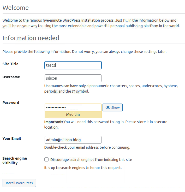
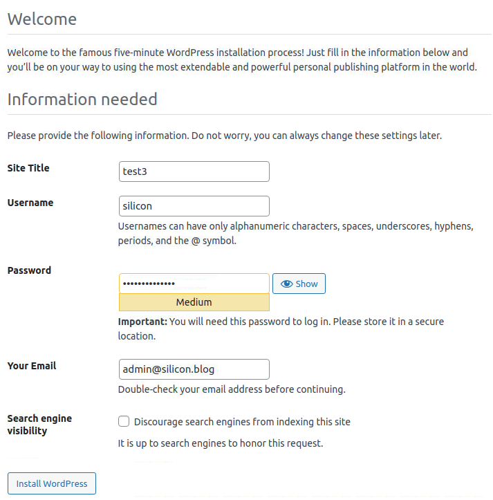
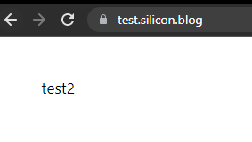
Step 6: Go to WordPress 2 container and WordPress 3 container to install WordPress. Use test2 and test3 as the Site Title.
http://your_ip:8081/
http://your_ip:8082/
Step 7: After installation, go to the Settings page, and change the WordPress Address (URL) and Site Address (URL) with your WordPress domain name. In my case, it is https://test.silicon.blog.
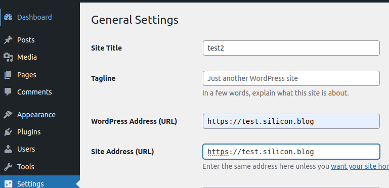
It is normal if your browser returns ‘your ip sent an invalid response’ errors.
Everything will be fine after configuring the Nginx Proxy Manager.
Step 8: Modify the proxy_host.conf of the Nginx Proxy Manager docker container. sudo nano ./templates/proxy_host.conf At the top {% if enabled %}, add the following lines
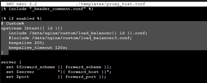
# Custom%
upstream lbtest{{ id }}{
   include /data/nginx/custom/load_balancer{{ id }}.conf;
   keepalive 200;
   keepalive_timeout 120s;
}
Ctrl + X to save the file.
Step 9: Edit proxy.conf and comment out everything. Those headers will be added manually later.
sudo nano ./conf.d/include/proxy.conf
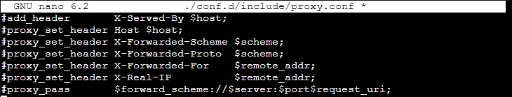
Ctrl + X to save the file.
Step 10: Since you will enable load balancing in Nginx Proxy Manager in a hacky way, the load balancer configuration file will not be generated automatically when we click save.
We have to add and edit the load balancer configuration manually. It may crash if Nginx Proxy Manager cannot find the related load_balancerX.conf or the load_balancerX.conf is empty at the start. Therefore, you need to create 10 load balancer configuration files and fill contents to them for later use by
sudo touch ./data/nginx/custom/load_balancer{1..10}.conf
echo "server 127.0.0.1 weight=1;" | sudo tee ./data/nginx/custom/load_balancer{1..10}.conf 1>/dev/null
You can generate as many load balancer configuration files as you want, but the Nginx Proxy Manager will take a long time to load if you create more than 100 load balancer configuration files.
Step 11: On the Nginx Proxy Manager dashboard, find out the number of your Proxy host.
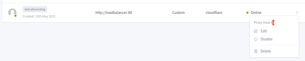
In my case, it is proxy host 3.
Step 12: Edit the load balancer configuration file matching the proxy host number. Replace X with your proxy host number. In my case, it is load_balancer3.conf.
sudo mkdir ./data/nginx/custom/
sudo nano ./data/nginx/custom/load_balancerX.conf
Add the WordPress server to the load balancer.
server your_wordpress_server1_ip:port weight=1;
server your_wordpress_server2_ip:port weight=1;
server your_wordpress_server3_ip:port weight=1;
In my case, it is
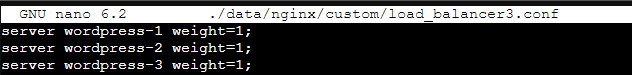
server wordpress-1 weight=1;
server wordpress-2 weight=1;
server wordpress-3 weight=1;
Ctrl + X to save the file.
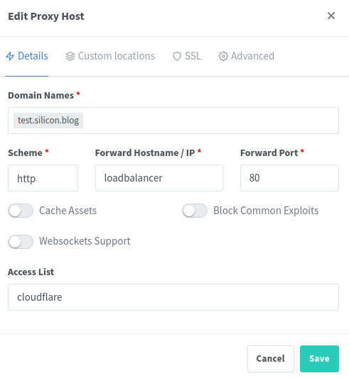
Step 13: Edit your proxy host. Change the Forward Hostname / IP to loadbalancer. The Forward Port does not matter. The scheme will be HTTP in this article, and you can change it to HTTPS later.
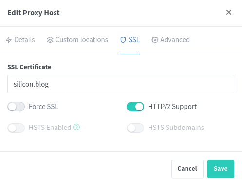
Step 14: Remember to add an SSL certificate to your site in the SSL section. HTTP/2 Support is optional.
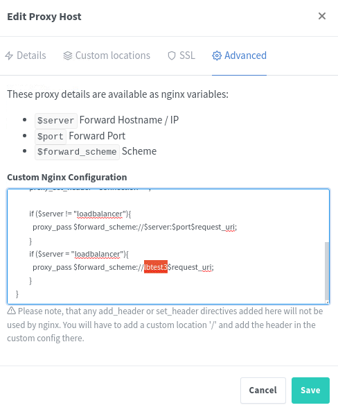
Step 15: Go to the Advanced page, and add the following script.
Replace lbtestX with your proxy host number. In my case, it is lbtest3.
If needed, you should return to step 10 and manually create more load balancer files.
Your Nginx Proxy Manager may crash at the start if it cannot find the corresponding load balancer file.
location / {
proxy_set_header Host $host;
proxy_set_header X-Forwarded-Host $server_name;
proxy_connect_timeout   15s;
proxy_read_timeout  15s;
proxy_next_upstream error timeout http_500 http_502 http_503 http_504 non_idempotent;
proxy_set_header    Connection  "";

if ($server != "loadbalancer"){
  proxy_pass $forward_scheme://$server:$port$request_uri;
}
if ($server = "loadbalancer"){
  proxy_pass $forward_scheme://lbtestX$request_uri;
}
}
In my case, it is
location / {
proxy_set_header Host $host;
proxy_set_header X-Forwarded-Host $server_name;
proxy_connect_timeout   15s;
proxy_read_timeout  15s;
proxy_next_upstream error timeout http_500 http_502 http_503 http_504 non_idempotent;
proxy_set_header    Connection  "";

if ($server != "loadbalancer"){
  proxy_pass $forward_scheme://$server:$port$request_uri;
}
if ($server = "loadbalancer"){
  proxy_pass $forward_scheme://lbtest3$request_uri;
}
}
Try to access your site a few times. The site title should change randomly if everything works properly.
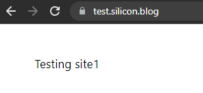
Congratulation if everything runs smoothly on your side.
The following article will teach you how to create a failover site using Nginx Proxy Manager and cPanel (or other web hosting platforms).
Check out this article if you want to enable HTTPS (install SSL certificate on your Apache server) on your WordPress docker container.
I am not using it in a large-scale high-traffic production site. Take risks if you use this method to load balance your web servers.
Feel free to comment on any potential security issues with the proxy header. I am not familiar with it.
Step-by-Step Guide to Load Balancing with Nginx Proxy Manager
Link: https://blog.devomkar.com/load-balancer-nginx-proxy-manager/
Load balancing is a crucial aspect of managing web traffic efficiently, ensuring high availability, and optimizing resource utilization. Nginx Proxy Manager is a powerful tool that simplifies the process of setting up and managing reverse proxies with load balancing capabilities. In this step-by-step guide, we'll walk through the process of configuring load balancing using Nginx Proxy Manager.
Prerequisites:
Step 1: Access Nginx Proxy Manager Web Interface
Open your web browser and navigate to the Nginx Proxy Manager web interface. Typically, it's accessible at http://your-server-ip:81. Log in using your credentials.
Step 2: Create Custom Configuration Snippet
cd /data/nginx/customtouch http_top.confnano http_top.confupstream backend {
server 192.168.0.69:8080;
server 192.168.0.100:8090 backup;
}Save the changes and exit the text editor.
Step 3: Add Custom Configuration in Nginx Proxy Manager
location / {
    proxy_pass http://backend;
}Step 4: Test and Verify
For more information on HTTP Load Balancing in NGINX click here.
Congratulations! You have successfully set up load balancing using custom Nginx configuration snippets in Nginx Proxy Manager. Adjust the configuration as needed and scale your infrastructure to handle increased traffic efficiently.
HTTP Load Balancing Nginx Configuration
Link: https://docs.nginx.com/nginx/admin-guide/load-balancer/http-load-balancer/?ref=blog.devomkar.com
Load balance HTTP traffic across web or application server groups, with several algorithms and advanced features like slow-start and session persistence.
Overview
Load balancing across multiple application instances is a commonly used technique for optimizing resource utilization, maximizing throughput, reducing latency, and ensuring fault‑tolerant configurations.
Watch the NGINX Plus for Load Balancing and Scaling webinar on demand for a deep dive on techniques that NGINX users employ to build large‑scale, highly available web services.
NGINX and NGINX Plus can be used in different deployment scenarios as a very efficient HTTP load balancer.
Proxying HTTP Traffic to a Group of Servers
To start using NGINX Plus or NGINX Open Source to load balance HTTP traffic to a group of servers, first you need to define the group with the upstream directive. The directive is placed in the http context.
Servers in the group are configured using the server directive (not to be confused with the server block that defines a virtual server running on NGINX). For example, the following configuration defines a group named backend and consists of three server configurations (which may resolve in more than three actual servers):
http {
    upstream backend {
        server backend1.example.com weight=5;
        server backend2.example.com;
        server 192.0.0.1 backup;
    }
}
To pass requests to a server group, the name of the group is specified in the proxy_pass directive (or the fastcgi_pass, memcached_pass, scgi_pass, or uwsgi_pass directives for those protocols.) In the next example, a virtual server running on NGINX passes all requests to the backend upstream group defined in the previous example:
server {
    location / {
        proxy_pass http://backend;
    }
}
The following example combines the two snippets above and shows how to proxy HTTP requests to the backend server group. The group consists of three servers, two of them running instances of the same application while the third is a backup server. Because no load‑balancing algorithm is specified in the upstream block, NGINX uses the default algorithm, Round Robin:
http {
    upstream backend {
        server backend1.example.com;
        server backend2.example.com;
        server 192.0.0.1 backup;
    }

    server {
        location / {
            proxy_pass http://backend;
        }
    }
}
Choosing a Load-Balancing Method
NGINX Open Source supports four load‑balancing methods, and NGINX Plus adds two more methods:
-
Round Robin – Requests are distributed evenly across the servers, with server weights taken into consideration. This method is used by default (there is no directive for enabling it):
upstream backend { # no load balancing method is specified for Round Robin server backend1.example.com; server backend2.example.com; } -
Least Connections – A request is sent to the server with the least number of active connections, again with server weights taken into consideration:
upstream backend { least_conn; server backend1.example.com; server backend2.example.com; } -
IP Hash – The server to which a request is sent is determined from the client IP address. In this case, either the first three octets of the IPv4 address or the whole IPv6 address are used to calculate the hash value. The method guarantees that requests from the same address get to the same server unless it is not available.
upstream backend {
    ip_hash;
    server backend1.example.com;
    server backend2.example.com;
}
If one of the servers needs to be temporarily removed from the load‑balancing rotation, it can be marked with the down parameter in order to preserve the current hashing of client IP addresses. Requests that were to be processed by this server are automatically sent to the next server in the group:
upstream backend { server backend1.example.com; server backend2.example.com; server backend3.example.com down; } -
Generic Hash – The server to which a request is sent is determined from a user‑defined key which can be a text string, variable, or a combination. For example, the key may be a paired source IP address and port, or a URI as in this example:
upstream backend {
    hash $request_uri consistent;
    server backend1.example.com;
    server backend2.example.com;
}
The optional consistent parameter to the
hashdirective enables ketama consistent‑hash load balancing. Requests are evenly distributed across all upstream servers based on the user‑defined hashed key value. If an upstream server is added to or removed from an upstream group, only a few keys are remapped which minimizes cache misses in the case of load‑balancing cache servers or other applications that accumulate state. -
Least Time (NGINX Plus only) – For each request, NGINX Plus selects the server with the lowest average latency and the lowest number of active connections, where the lowest average latency is calculated based on which of the following parameters to the
least_timedirective is included:header– Time to receive the first byte from the serverlast_byte– Time to receive the full response from the serverlast_byte inflight– Time to receive the full response from the server, taking into account incomplete requests
upstream backend { least_time header; server backend1.example.com; server backend2.example.com; } -
Random – Each request will be passed to a randomly selected server. If the
twoparameter is specified, first, NGINX randomly selects two servers taking into account server weights, and then chooses one of these servers using the specified method:least_conn– The least number of active connectionsleast_time=header(NGINX Plus) – The least average time to receive the response header from the server ($upstream_header_time)least_time=last_byte(NGINX Plus) – The least average time to receive the full response from the server ($upstream_response_time)
upstream backend {
    random two least_time=last_byte;
    server backend1.example.com;
    server backend2.example.com;
    server backend3.example.com;
    server backend4.example.com;
}
The Random load balancing method should be used for distributed environments where multiple load balancers are passing requests to the same set of backends. For environments where the load balancer has a full view of all requests, use other load balancing methods, such as round robin, least connections and least time.
Note: When configuring any method other than Round Robin, put the corresponding directive (
hash,ip_hash,least_conn,least_time, orrandom) above the list ofserverdirectives in theupstream {}block.
Server Weights
By default, NGINX distributes requests among the servers in the group according to their weights using the Round Robin method. The weight parameter to the server directive sets the weight of a server; the default is 1:
upstream backend {
    server backend1.example.com weight=5;
    server backend2.example.com;
    server 192.0.0.1 backup;
}
In the example, backend1.example.com has weight 5; the other two servers have the default weight (1), but the one with IP address 192.0.0.1 is marked as a backup server and does not receive requests unless both of the other servers are unavailable. With this configuration of weights, out of every 6 requests, 5 are sent to backend1.example.com and 1 to backend2.example.com.
Server Slow-Start
The server slow‑start feature prevents a recently recovered server from being overwhelmed by connections, which may time out and cause the server to be marked as failed again.
In NGINX Plus, slow‑start allows an upstream server to gradually recover its weight from 0 to its nominal value after it has been recovered or became available. This can be done with the slow_start parameter to the server directive:
upstream backend {
    server backend1.example.com slow_start=30s;
    server backend2.example.com;
    server 192.0.0.1 backup;
}
The time value (here, 30 seconds) sets the time during which NGINX Plus ramps up the number of connections to the server to the full value.
Note that if there is only a single server in a group, the max_fails, fail_timeout, and slow_start parameters to the server directive are ignored and the server is never considered unavailable.
Enabling Session Persistence
Session persistence means that NGINX Plus identifies user sessions and routes all requests in a given session to the same upstream server.
NGINX Plus supports three session persistence methods. The methods are set with the sticky directive. (For session persistence with NGINX Open Source, use the hash or ip_hash directive as described above.)
Limiting the Number of Connections
With NGINX Plus, it is possible to limit the number of active connections to an upstream server by specifying the maximum number with the max_conns parameter.
If the max_conns limit has been reached, the request is placed in a queue for further processing, provided that the queue directive is also included to set the maximum number of requests that can be simultaneously in the queue:
upstream backend {
    server backend1.example.com max_conns=3;
    server backend2.example.com;
    queue 100 timeout=70;
}
If the queue is filled up with requests or the upstream server cannot be selected during the timeout specified by the optional timeout parameter, the client receives an error.
Note that the max_conns limit is ignored if there are idle keepalive connections opened in other worker processes. As a result, the total number of connections to the server might exceed the max_conns value in a configuration where the memory is shared with multiple worker processes.
Configuring Health Checks
NGINX can continually test your HTTP upstream servers, avoid the servers that have failed, and gracefully add the recovered servers into the load‑balanced group.
See HTTP Health Checks for instructions how to configure health checks for HTTP.
Sharing Data with Multiple Worker Processes
If an upstream block does not include the zone directive, each worker process keeps its own copy of the server group configuration and maintains its own set of related counters. The counters include the current number of connections to each server in the group and the number of failed attempts to pass a request to a server. As a result, the server group configuration cannot be modified dynamically.
When the zone directive is included in an upstream block, the configuration of the upstream group is kept in a memory area shared among all worker processes. This scenario is dynamically configurable, because the worker processes access the same copy of the group configuration and utilize the same related counters.
The zone directive is mandatory for active health checks and dynamic reconfiguration of the upstream group. However, other features of upstream groups can benefit from the use of this directive as well.
For example, if the configuration of a group is not shared, each worker process maintains its own counter for failed attempts to pass a request to a server (set by the max_fails parameter). In this case, each request gets to only one worker process. When the worker process that is selected to process a request fails to transmit the request to a server, other worker processes don’t know anything about it. While some worker process can consider a server unavailable, others might still send requests to this server. For a server to be definitively considered unavailable, the number of failed attempts during the timeframe set by the fail_timeout parameter must equal max_fails multiplied by the number of worker processes. On the other hand, the zone directive guarantees the expected behavior.
Similarly, the Least Connections load‑balancing method might not work as expected without the zone directive, at least under low load. This method passes a request to the server with the smallest number of active connections. If the configuration of the group is not shared, each worker process uses its own counter for the number of connections and might send a request to the same server that another worker process just sent a request to. However, you can increase the number of requests to reduce this effect. Under high load requests are distributed among worker processes evenly, and the Least Connections method works as expected.
Setting the Zone Size
It is not possible to recommend an ideal memory‑zone size, because usage patterns vary widely. The required amount of memory is determined by which features (such as session persistence, health checks, or DNS re‑resolving) are enabled and how the upstream servers are identified.
As an example, with the sticky_route session persistence method and a single health check enabled, a 256‑KB zone can accommodate information about the indicated number of upstream servers:
- 128 servers (each defined as an IP‑address:port pair)
- 88 servers (each defined as hostname:port pair where the hostname resolves to a single IP address)
- 12 servers (each defined as hostname:port pair where the hostname resolves to multiple IP addresses)
Configuring HTTP Load Balancing Using DNS
The configuration of a server group can be modified at runtime using DNS.
For servers in an upstream group that are identified with a domain name in the server directive, NGINX Plus can monitor changes to the list of IP addresses in the corresponding DNS record, and automatically apply the changes to load balancing for the upstream group, without requiring a restart. This can be done by including the resolver directive in the http block along with the resolve parameter to the server directive:
http {
    resolver 10.0.0.1 valid=300s ipv6=off;
    resolver_timeout 10s;
    server {
        location / {
            proxy_pass http://backend;
        }
    }
    upstream backend {
        zone backend 32k;
        least_conn;
        # ...
        server backend1.example.com resolve;
        server backend2.example.com resolve;
    }
}
In the example, the resolve parameter to the server directive tells NGINX Plus to periodically re‑resolve the backend1.example.com and backend2.example.com domain names into IP addresses.
The resolver directive defines the IP address of the DNS server to which NGINX Plus sends requests (here, 10.0.0.1). By default, NGINX Plus re‑resolves DNS records at the frequency specified by time‑to‑live (TTL) in the record, but you can override the TTL value with the valid parameter; in the example it is 300 seconds, or 5 minutes.
The optional ipv6=off parameter means only IPv4 addresses are used for load balancing, though resolving of both IPv4 and IPv6 addresses is supported by default.
If a domain name resolves to several IP addresses, the addresses are saved to the upstream configuration and load balanced. In our example, the servers are load balanced according to the Least Connections load‑balancing method. If the list of IP addresses for a server has changed, NGINX Plus immediately starts load balancing across the new set of addresses.
Load Balancing of Microsoft Exchange Servers
In NGINX Plus Release 7 and later, NGINX Plus can proxy Microsoft Exchange traffic to a server or a group of servers and load balance it.
To set up load balancing of Microsoft Exchange servers:
-
In a
locationblock, configure proxying to the upstream group of Microsoft Exchange servers with theproxy_passdirective:location / { proxy_pass https://exchange; # ... } -
In order for Microsoft Exchange connections to pass to the upstream servers, in the
locationblock set theproxy_http_versiondirective value to1.1, and theproxy_set_headerdirective toConnection "", just like for a keepalive connection:location / { # ... proxy_http_version 1.1; proxy_set_header Connection ""; # ... } -
In the
httpblock, configure a upstream group of Microsoft Exchange servers with anupstreamblock named the same as the upstream group specified with theproxy_passdirective in Step 1. Then specify thentlmdirective to allow the servers in the group to accept requests with NTLM authentication:http { # ... upstream exchange { zone exchange 64k; ntlm; # ... } } -
Add Microsoft Exchange servers to the upstream group and optionally specify a load‑balancing method:
http {
    # ...
    upstream exchange {
        zone exchange 64k;
        ntlm;
        server exchange1.example.com;
        server exchange2.example.com;
        # ...
    }
}
Complete NTLM Example
http {
    # ...
    upstream exchange {
        zone exchange 64k;
        ntlm;
        server exchange1.example.com;
        server exchange2.example.com;
    }

    server {
        listen              443 ssl;
        ssl_certificate     /etc/nginx/ssl/company.com.crt;
        ssl_certificate_key /etc/nginx/ssl/company.com.key;
        ssl_protocols       TLSv1 TLSv1.1 TLSv1.2;

        location / {
            proxy_pass         https://exchange;
            proxy_http_version 1.1;
            proxy_set_header   Connection "";
        }
    }
}
For more information about configuring Microsoft Exchange and NGINX Plus, see the Load Balancing Microsoft Exchange Servers with NGINX Plus deployment guide.
Dynamic Configuration Using the NGINX Plus API
With NGINX Plus, the configuration of an upstream server group can be modified dynamically using the NGINX Plus API. A configuration command can be used to view all servers or a particular server in a group, modify parameter for a particular server, and add or remove servers. For more information and instructions, see Configuring Dynamic Load Balancing with the NGINX Plus API.
Understanding nginx $request_uri
Link: https://stackoverflow.com/questions/48708361/nginx-request-uri-vs-uri
As we came across this question often ourselves, I decided to write a quick article about the $request_uri handling of nginx. According to the ngx_http_core_module-documentation, the variable $request_uri is defined as:
full original request URI (with arguments)
While this seems clear at first, it is not well defined. We have done some trial and error and can best explain it by examples using real cases:
- For the URL:
https://www.webhosting24.com/understanding-nginx-request_uri/
the nginx variable $request_uri is populated as follows:
/understanding-nginx-request_uri/ - For the URL:
https://www.webhosting24.com/cp/cart.php?a=add&domain=register
the nginx variable $request_uri is populated as follows:
/cp/cart.php?a=add&domain=register - For the URL:
https://www.w3.org/Protocols/rfc2616/rfc2616-sec3.html#sec3.2
the nginx variable $request_uri would still be populated only as follows:
/Protocols/rfc2616/rfc2616-sec3.html
as #sec3.2 is just a fragment/comment/anchor and not part of the URI.
Simply put, the $request_uri contains the full path (/understanding-nginx-request_uri/ in example 1 or /cp/cart.php in example 2 above) and any argument strings that may be present (“?a=add&domain=register” in example 2 above), but excludes the schema (https:// and the port (implicit 443) in both examples above) as defined by RFC for the URL:
http_URL = "http(s):" "//" host [ ":" port ] [ abs_path [ "?" query ]]
Uniform Resource Identifiers
By RFC URIs have been known by many names: WWW addresses, Universal Document Identifiers, Universal Resource Identifiers, and finally the combination of Uniform Resource Locators (URL). As far as HTTP is concerned, Uniform Resource Identifiers are simply formatted strings which identify–via name, location, or any other characteristic–a resource.
Further Sources:
https://www.w3.org/Protocols/rfc2616/rfc2616-sec3.html#sec3.2
http://nginx.org/en/docs/http/ngx_http_core_module.html#var_request_uri